

Part 1 of the Easy Encoder Guide reviewed what an encoder is, the differences between types of...

Part 1 of this guide covered what an encoder is and differentiated the types of encoders as well as the different output configurations. In addition, optical rotary encoders were explained and difference between the operation of incremental and absolute encoders. Part 2 of the Encoder Guide will continue to focus on the different types of rotary encoders and how they operate.
How do Magnetic Rotary Encoders Work?
Magnet technology can be found in increasingly innovative applications. A magnetic encoder consists of two parts: a rotor and a sensor. The rotor turns with the shaft and contains alternating evenly spaced north and south poles around its circumference. The sensor detects these small shifts in the position N>>S and S>>N. See Figure 3.
There many methods of detecting magnetic field changes, but the two primary types used in encoders are: Hall-Effect and Magneto resistive.
Hall-Effect sensors work by detecting a change in voltage by magnetic deflection of electrons. Magneto resistive sensors detect a change in resistance caused by a magnetic field.

Figure 3 – Basic Principal of a Magnetic Rotary Encoder
With Hall-Effect sensing (the more common of the two methods) the sensor produces and processes Hall-Effect signals, producing a quadrature signal as is common with optical encoders. The output is generated by measuring magnetic flux distributions across the surface of the sensing chip. (See Figure 4) The output accuracy is dependent on the radial placement of the IC with respect to the target magnet. The chip face should be parallel to the magnet so the magnet-to-sensor air gap is consistent across the sensor face.
Magnetic encoders avoid the 3 vulnerabilities that optical encoders face:
- Seal failures which permit the entry of contaminants or fluids
- The optical disk may shatter during vibration or impact
- Bearing failures
Magnetic devices designed effectively eliminate the first two failure modes and offer an opportunity to reduce bearing failures as well. Magnetic encoders do not make errors due to contamination because their sensors detect variations in magnetic fields imbedded in the rotor — oil, dirt and water do not affect these magnetic fields.
A = Target Radius; B=Pitch Radius

Figure 4 – Construction of a Magnetic Rotary Encoder
Hall-Effect sensors generally have lower cost and are less precise than magnetic resistive sensors. This means that Hall-Effect sensors, when used in an encoder produce more "jitter", or error in the signal caused by sensor variations.
What is a Commutation Encoder and How Do They Work?
A commutation encoder contains the same fundamental components as incremental optical encoders, but with the addition of commutation tracks alongside the outer edge of the disk for U/V/W output.
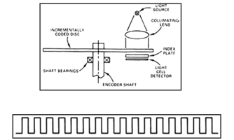
Commutation encoders utilize a transparent disk which includes opaque sections that are equally spaced to determine movement. A light emitting diode or LED light passes through the glass disk and is detected by a photo detector. This causes the encoder to generate a train of equally spaced pulses as it rotates. The output of incremental rotary encoders is measured in pulses per revolution, which is used to keep track of position or determine speed. If needed, refer to Part 1 of the Encoder Guide posted earlier.
The outer part of the encoder disk includes commutation tracks which provide a controller with information on the exact position of the motor poles, so that the proper controller input can be supplied to the motor. The commutation tracks of the encoder read the motor position and instruct the controller as to how to provide efficient and proper current to the motor to cause rotation. Commutation output for U/V/W can be in the form of differential output or open-collector (manufacturer dependent).
How are Rotary Encoders Controlled?
Rotary encoders are controlled through the rotation of the shaft that the encoder is mounted to. The shaft comes into contact with a hub which is in internal to the encoder. As the shaft rotates, it causes the disc to rotate across the circuitry of the encoder. The circuitry of the encoder interprets the rotation of the disc and outputs pulses to the user. The speed at which the disc rotates will be dependent on the speed of the shaft the encoder is connected to.
Conclusion
Now that we've looked at the functions of rotary encoders, we can next consider Linear Encoders and the best applications.
Stay tuned for Part 3 of the Easy Encoder Guide!
In the meantime, if you have any questions about using encoders or you're seeking consultation for your next project, contact our experienced staff for a free consultation.

You may also be interested in reading:
- Easy Encoder Guide: Part 1
- LED Lighting Case Study: Donjon Shipbuilding
- The 4 Pillars of Industrial Network Support